






// STRUCTURAL · FLUID · THERMAL · VIBRO-ACOUSTIC

We solve for the decision, not for the mesh.

Verified FEM, CFD and NVH analysis for teams who need a defensible answer — traceable to the governing equations and to the standard it must pass.

σ_vM ≤ f_y / γ_M0 → PASS

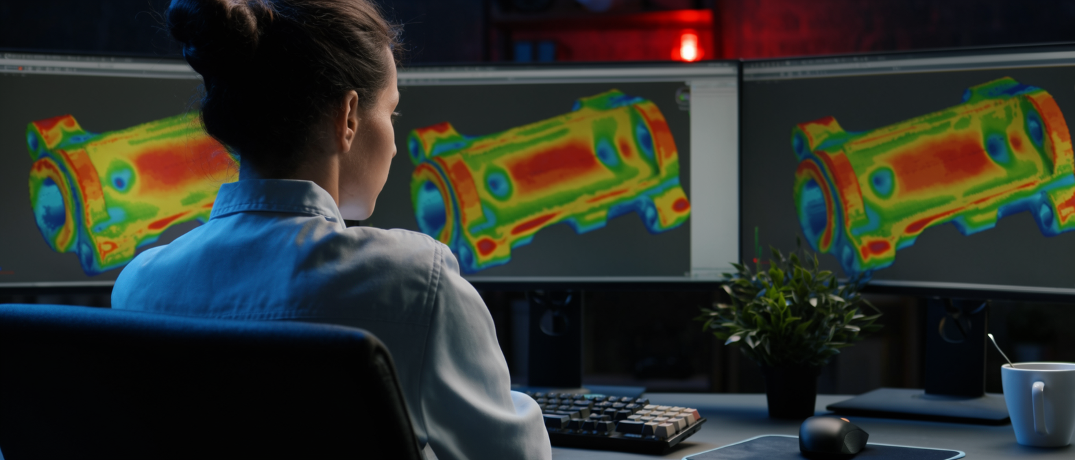
FIG. 1 — [Stress Distribution Contour] σ_vM [MPa]
L = [___] mm σ_max · re-entrant corner
DWG BMX-000 REV A SHEET 1/1 CHECKED ✓
FIELD EXPERIENCE [15] yrs
PROJECTS DELIVERED [212]+
PHYSICS DOMAINS 06
INDUSTRIES 08
STANDARD FAMILIES ISO · ASCE · EN · MIL

01 / CAPABILITIES

Six physics domains. One governing standard of rigour.

Full capability sheet (PDF) ↓
S-01 · STRUCTURALSPEC →

[K]{u} = {F}

METHODS
Linear & nonlinear static · contact · buckling · fatigue (S-N, ε-N)
OUTPUT
Stress & deflection fields, utilisation ratios, fatigue life
REFERENCE
EN 1993 · EN 1998 · ASCE 7
S-02 · FLUIDSPEC →

∂(ρu)/∂t + ∇·(ρu⊗u) = −∇p + ∇·τ

METHODS
RANS · URANS · LES · species transport · mixing
OUTPUT
Pressure & velocity fields, forces, load maps for FEM
REFERENCE
ASCE 7 (wind) · [confirm]
S-03 · DYNAMICSSPEC →

([K] − ω²[M]){φ} = 0

METHODS
Modal · harmonic · random (PSD) · shock (SRS)
OUTPUT
Mode shapes, FRFs, PSD response, resonance margins
REFERENCE
MIL-STD-810 · ISO 20816
S-04 · THERMALSPEC →

ρc_p ∂T/∂t = ∇·(k∇T) + q̇

METHODS
Steady · transient · conjugate heat transfer · radiation
OUTPUT
Temperature fields, heat flux, thermo-mechanical stress
REFERENCE
[Applicable standard]
S-05 · ACOUSTICSPEC →

∇²p − (1/c²) ∂²p/∂t² = 0

METHODS
Radiated noise · transmission loss · vibro-acoustic coupling
OUTPUT
SPL maps, sound power, TL curves
REFERENCE
[Applicable standard]
S-06 · CONCEPTSPEC →

min f(x) s.t. g(x) ≤ 0

METHODS
Topology & parametric optimisation · DoE · trade studies
OUTPUT
Simulation-validated concept geometry
REFERENCE
Project-specific

02 / VERIFICATION & VALIDATION

Every result is defended before it is delivered.

A colourful contour plot proves nothing. Each deliverable passes four checks, and the evidence ships in the report.
V1
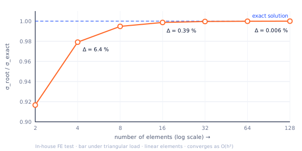
Mesh independenceThe result is shown to stop moving as the mesh is refined.
V2
Boundary conditions justifiedEvery constraint and load is traced back to a physical source.
V3
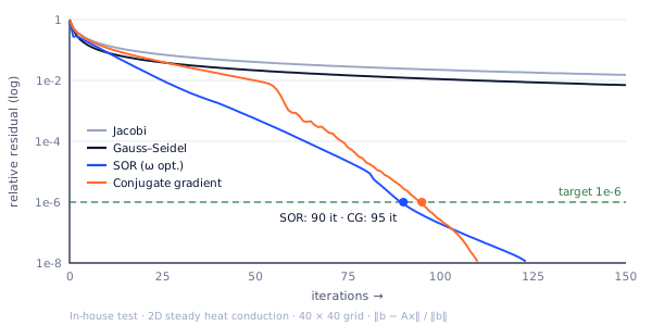
Solver convergenceResiduals and energy balances are reported, not hidden.
V4
Checked against the codeThe margin against the governing standard is stated explicitly.
FIG. 2 — Mesh independence studyV1
fig2-mesh-independence
FIG. 3 — Residual convergenceV3
fig3-residual-convergence

03 / PROCESS

Filter first. Then compute.

Inputs that do not change the engineering decision are removed before a single element is meshed.

  1. 01

    Filter the inputs

    We start from the decision you need to make, and keep only the loads, geometry and material data that actually change it.

  2. 02

    Model and verify

    Mesh independence and sanity checks come before any result is shown. If the model cannot be verified, it is not used.

  3. 03

    Validate against the standard

    Every result is checked against the code or standard the part must pass, with the margin stated.

  4. 04

    Report the decision

    You get the answer, the assumptions behind it and the traceable path from equation to conclusion.

07 / INDUSTRIES

Load cases we know by heart.

07 / WHY BADGERMECX

Why teams bring the hard ones to us.

01

We filter the inputs

Most analysis time is lost on data that does not change the answer. We decide what matters before we build the model.

02

Verification is not optional

Mesh independence, residuals and sanity checks are part of every job, not an extra.

03

Traceable to the standard

Each result is tied to the code it must satisfy, so your reviewer can follow the same path.

04

Engineers, not a render farm

You talk to the person who ran the analysis and can defend it.

05 / STANDARDS

Standards we work to.

Keep only the standards you actually work to — remove the rest.

Keep only the standards you actually work to — remove the rest.

EN 1993Eurocode 3 — design of steel structuresStructural
EN 1998Eurocode 8 — earthquake resistanceStructural
ASCE 7Minimum design loads (wind, seismic)Structural · CFD
MIL-STD-810Environmental engineering — vibration and shockNVH
ISO 20816Mechanical vibration — measurement and evaluationNVH

06 / OUR TEAM

Meet the people behind the numbers.

Engineers who spent years in the field before moving to the screen. The person you brief is the person who runs your model.

Meet the whole team →

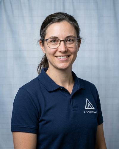
Ryan N. Hildebrand
Ryan N. Hildebrand Chief Technology Officer Reviews every model before it leaves the building. Nothing ships unchecked. Sets the methods, checks the assumptions, signs the report. Technical reviewV&V sign-off
Sarah M. Ray
Sarah M. Ray Head of Engineering Turns your brief into a scoped, scheduled analysis plan, and keeps it on track. Your single point of contact from first call to final report. Project deliveryClient scopingQA & reporting
Pelin Akçakoca
Pelin Akçakoca Team Lead · NVH & Dynamics Finds the resonance before your test rig does. Modal, random vibration and shock, from mesh to fatigue life. ModalRandom vibration
Micheal Burnett
Micheal Burnett Team Lead · Thermal & Multiphysics Couples heat, flow and current until the physics agrees. When one solver isn't enough: thermal, electric and fluid, in one model. CHTThermo-electricTransient
WE'RE HIRING Want to solve hard problems with us? Senior CFD & Thermal Systems Engineer
Careers →

09 / FROM THE BLOG

From the blog

All articles →

09 / PROBLEM STATEMENT

Define the decision. We'll define the model.

Send the load case, the geometry format and the standard it must pass. You'll get a scoped, fixed deliverable back.

  • [✓] NDA before data exchange
  • [✓] Response within 2 business day(s)
  • [✓] Scope, assumptions & acceptance criteria in writing